AI on the Edge: Microchip's SAM E54 Xplained Pro
Image Source: RedlineVector/shutterstock.com
By Michael Parks for Mouser Electronics
Edited September 2, 2021 (Originally Published June 12, 2020)
Introduction
Second of a four-part series examining the convergence of embedded electronics and artificial
intelligence (AI).
Combining efficient, brain-like algorithms and inexpensive yet powerful microcontrollers and sensors has given
rise to so-called edge computing. Edge computing promises billions of inexpensive embedded electronic systems
interacting with the physical world nearly instantaneously. In addition, reaching back to the processing
horsepower of the cloud is not needed. When fully realized, edge computing represents a revolution in
automation, both in scale and capability.
One such capability is the desire for these edge devices to augment the human worker by being a watchful
protector that never blinks. One example: a function that turns off heavy machinery should someone place their
hand in an unsafe location. This project will look at how machine learning can be applied to image
detection use-cases in a practical and meaningful manner.
Project Materials and Resources
In this next chapter of our TensorFlow Lite for Microcontrollers series, we will focus on the SAM E54 Xplained
Pro evaluation kit (Figure
1); a hardware platform for evaluating the ATSAME54P20A microcontroller.
Figure 1: Microchip Technology’s SAM E54 Xplained Pro Development Kit is a
hardware platform for evaluating the ATSAME54P20A microcontroller. (Source: Microchip Technology)
We will leverage the SAM E54 to build a device that incorporates a camera as an input device and an LED as user
feedback. The goal is to toggle the LED on and off depending on whether a human is within the camera’s
field of view.
Bill of Material (BOM)
You can click this Mouser
project share link to access the BOM along with the current pricing. Table 1 lists the
items in the BOM.
Table 1: TensorFlow Lite - Microchip Technology BOM
| Quantity |
Mouser P/N |
Description |
Notes |
| 1 |
556-ATSAME54XPRO (Figure 2) |
Development Boards & Kits - ARM SAM E54 XPLAINED PRO |
|
| 1 |
713-114991881 |
OV2640 Camera |
|
| 4 |
667-ERJ-2GE0R00X |
0-ohm resistors, 0402 package, 1/16W |
R205, R206, R207, R208 |
| 1 |
932-MIKROE-2295 |
24-pin FPC Cable |
Between OV2640 and Adapter Board FPC |
| 1 |
200-IDSD05D0300T |
2x10 IDC Cable, 0.1" pitch, 3" length |
Between SAM E54 and Adapter Board PCC |
| 2 |
200-MTSW10508LD335 |
2x10 male header |
SAM E54 PCC
Adapter Board PCC |
| 1 |
798-FH12-24S-0.5SH55 |
Hirose 1x24 FPC |
Adapter Board FPC |
Resources
All source files for this project are located on Mouser’s GitHub
repository.
The repository is divided into three main folders:
Figure 2: A schematic view of the SAM E54 Xplained Pro development board.
(Source: Microchip Technology)
Documentation
The Documentation folder contains graphic files of schematics (Figure 2) and other
important reference materials.
Hardware
The Hardware folder contains schematics of the SAM E54 development board and the OV2640
camera. It also includes
the schematic capture and printed circuit board (PCB) layout files for an adapter board to connect the OV2640
camera's FPC cable to the SAM E54's 2x10 printed-circuit-board connector (PCC) connector. The board layout was
done in KiCAD, a free and
open-source schematic capture and board layout application that can be downloaded here.
Figure 3: The PCB and enclosure for camera adapter board. (Source: MB
Parks)
3D Files
The 3D Files folder contains 3D renderings (.f3d, .step) of the adapter board PCB as
well as the files needed to
view and 3D print (.stl, .obj) a custom stand for the adapter board to keep it safe (Figure
3).
The files can be viewed for free here.
If you would like to purchase the PCB, it is available at OSHPark.
The FPC connector and male headers that must be soldered onto the PCB are included in BOM.
Software
The Software folder contains the source code and the neural network model for the project. We will
have to modify
replace a few files with our custom implementation to interact with SAM E54 Xplained Pro development board and
associated components (LED and camera interface). The files provided:
- main.cc
- main_functions.cc / .h
- detection_responder.cc / .h
- image_provider.cc / .h
- driver_init.cc / .h
- model_settings.cc / .h
- atmel_start_pins.h
- no_person_image_data.h
- person_detect_model_data.h
- person_image_data.h
More details about these files can be found in the Software section below.
Tools
This project assumes that you have access to the following tools:
- Windows 7-based computer or newer with at least a 1.6GHz processor, 2GB RAM (another 512MB if using a
virtual machine), and 6GB of available storage.
- Internet connection
- Soldering iron
- Magnifying glass
- Flush diagonal cutter
- Needle-nose pliers
- Digital Multimeter (DMM)
Documentation
Additional resources and documentation regarding the Xplained Pro series of development boards and the
TensorFlow Lite for Microcontrollers Software Development Kit (SDK) are available. Some of the recommended
documentation to review:
https://www.tensorflow.org/lite/microcontrollers
A
wealth of information on TensorFlow Lite, machine learning, and getting started with the example models.
https://www.microchip.com/developmenttools/ProductDetails/atsame54-xpro
Links
to everything you need to know about the SAM E54 development board.http://ww1.microchip.com/downloads/en/DeviceDoc/SAM_E54_Xplained_Pro_Design_Documentation.zip
Contains
detailed information about the hardware design of the SAM E54 development board, including pin assignments,
schematics, and functional block diagrams.http://ww1.microchip.com/downloads/en/DeviceDoc/Getting-Started-with-Atmel-Studio7.pdf
A
good overview of how to use the Atmel Studio 7 integrated development environment.
Machine Learning Technology Overview
The SAM E54 Xplained Pro Development Board (Figure 4) features a powerful ATSAME54P20A
microcontroller with 32MB of Queued Serial Peripheral Interface (QSPI) Flash. The Xplained Pro development kits
include an onboard Embedded Debugger to simplify programming and troubleshooting.
Figure 4: Feature highlight of the SAM E54 Xplained Pro Development Boards.
(Source: Microchip Technology)
Google offers several pre-trained neural network models that will work with the
TensorFlow Lite for
Microcontroller SDK (Figure 5). They are available at
https://www.tensorflow.org/lite/microcontrollers/get_started
Figure 5: Google's TensorFlow Lite for Microcontroller website has resources
and pre-trained models ready for use. (Source: Google)
This project will go with the person detection example. This image recognition model will leverage the
development kit’s PCC connector to interface with the OV2640 camera module. The camera will provide inputs
for the TensorFlow object detection model.
To deploy a TensorFlow model to a microcontroller, you will need to follow this development workflow to train the
Neural Network (NN) model then convert it to a format that can work on a resource-constrained device such as a
microcontroller.
- Train the Neural Network: The TensorFlow framework allows a model to be trained on a
desktop computer or using the horsepower of cloud-based services such as Amazon Web Services (AWS) or Google
Compute Engine. Bottom line: the more processing power (CPUs and GPUs) you throw at training an NN, the
faster or more robust the final model will be. The result of training a model with TensorFlow is a file with
a .pb extension. Downloading a pre-trained model is another option.
- Prepare the Model for Inferencing Hardware: The next step is to take the trained model and
prepare it to run on the chosen endpoint device. The model must be made small enough to fit within the
memory of the SAM E54 after conversion. Additionally, the code can only use the functions supported by
TensorFlow Lite for Microcontrollers. However, it is possible to use a function not currently supported if
you write your custom implementations.
- Convert the TensorFlow model to a TensorFlow Lite FlatBuffer: You will convert your
model into the standard TensorFlow Lite format using the TensorFlow Lite converter. You might wish to
output a quantized model because these are smaller and more efficient to execute.
- Convert the FlatBuffer to a C Byte Array: Models are kept in read-only program memory
and stored in a C file. TensorFlow SDK provides tools that can be used to convert the FlatBuffer into
the appropriate C byte array format.
- Integrate the TensorFlow Lite for Microcontrollers C++ Library: Write the value-added code
for our particular implementation that will allow the project to interact with the accelerometer chip to
collect acceleration data, perform inferencing utilizing the TensorFlow Lite for Microcontroller C++
library, make a prediction, and then display the results to the end-user via the serial terminal.
- Deployment to the Edge: Build and deploy the program to your device using the Atmel Studio
7 IDE.
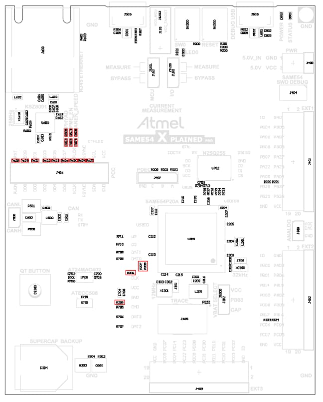
Figure 6: SAM E54 board layout with required resistor modifications
highlighted in red. (Source: Microchip Technology)
Putting It All Together
In this section, we will examine the necessary steps to get your project up and running. We will also point out
areas where you can customize the project to meet your specific needs. This project offers some rather good
opportunities to tweak the design to meet your specific needs.
The section is broken down into the following subsections:
- Hardware Modifications
- Setting up the Toolchain
- Software Development
Hardware Modifications
The SAM E54 contains a Parallel Capture Controller (PCC) to interact with the OV2460 camera. The physical form
factor is a 2x10, 100mm pitch pin-header. By default, the PCC connector is not functional because other
components are using the pins aboard the development board. These functions include Ethernet, QTouch, SD Card,
EXT1, and EXT2. To use the PCC, we will lose the ability to use these other functions.
The good news is this project allows us to practice two important electronics skills–desoldering and
soldering surface mount components. To enable the PCC functionality, the following modifications (Figure
6) to the dev board will be required:
- Remove the following surface mount resistors: R621, R622, R623, R624, R625, R626, R628, R629, R630, R308
- Insert the 2x10 male header (or two 1x10 male headers) through the top of the board and solder the pins from
the bottom of the board. (Figure 7)
- Solder 0Ω resistors to the following pads: R205, R206, R207, R208. The resistor package size is 0402
and must be rated for 1/16W at a minimum.
- Remove any SD cards from the SD card connector
Figure 7: The SAM E54 development board with male headers for the camera
interface now soldered on. (Source: Mouser Electronics)
Figure 8: PCB layout of the adapter board. (Source: MB Parks)
Next, we will solder the adapter board. It is very straightforward and requires soldering both through-hole
components and surface mount components. Just solder the surface-mount FPC connector to the FPC pads. Then place
the 2x10 male headers through the holes on top of the board and then solder them from the bottom of the board.
The adapter board (Figure 8) lets the FPC cable of the OV2640 camera connect to the PCC
connector board the SAM E54 development board. Table 2 shows the relationship of the OV2640
pins between the PCC connector and the FPC connector.
Table 2: PCC (IDC Cable) to FPC Pin Assignment Crosswalk
| PCC (IDC) Pin # |
Function |
FPC Pin # |
| 1 |
VCC |
10 |
| 2 |
GND |
15 |
| 3 |
SCL |
5 |
| 4 |
SDA |
3 |
| 5 |
VSYNC |
7 |
| 6 |
HSYNC |
9 |
| 7 |
PCLK |
17 |
| 8 |
XCLK |
13 |
| 9 |
DOUT07 |
16 |
| 10 |
DOUT06 |
18 |
| 11 |
DOUT05 |
20 |
| 12 |
DOUT04 |
22 |
| 13 |
DOUT03 |
21 |
| 14 |
DOUT02 |
19 |
| 15 |
DOUT01 |
23 |
| 16 |
DOUT00 |
24 |
| 17 |
DOUT09 |
12 |
| 18 |
DOUT08 |
14 |
| 19 |
RESET |
6 |
| 20 |
PDWN |
8 |
| N/A |
STROBE |
1 |
| N/A |
AGND |
2 |
| N/A |
AVDD |
4 |
| N/A |
DOVDD |
11 |
Setting up the Toolchain
When it comes to development environments for writing the firmware needed for this
project, two options are available:
- Atmel Studio 7
- MPLAB X IDE 5.XX
For this project, we will use Atmel Studio 7. But to begin, we will head over to Atmel’s START website (Figure
9) to grab the libraries that we need to interact with the SAM E54 development kit.
Figure 9: The Atmel START website allows an embedded developer to pick the
libraries for their target board. (Source: Microchip Technology)
Once there, follow these steps:
- Click on the green button labeled
Create New Project
- Look for the dialog box labeled
Filter on Device and enter E54
- Select
SAM E54 Xplained Pro
- Under
Drivers place a 1 next to Camera
- Select
Create New Project
- Click
Export Project
- Ensure
Atmel Studio is ticked
- Click
Download Pack to download the .atzip file that contains the code to be
imported into Atmel Studio 7.
Next, it is time to download Atmel Studio 7 (Figure 10).
Figure 10: Atmel Studio 7 is a convenient tool to edit your code and
interact with the SAM E54 Xplained Pro development board. (Source: Microchip Technology)
Next, grab a copy of the source code from our GitHub repository. Open your command prompt, navigate to where you
want to save the source code, then enter the following command:
#git clone https://github.com/Mouser-Electronics/TensorFlow-Lite-Microchip
Once we have the software installed and libraries downloaded, we can launch Atmel Studio 7 (Figure
11).
Figure 11: Atmel Studio 7 when initially launched. (Source: Microchip
Technology)
From the Atmel Studio 7 IDE, click file > open and then navigate to where you cloned the
repository and select
the project files (.cc/.h). With that, we are ready to examine the source code.
Software Development
Figure 12: Source code available on GitHub. (Source: Mouser
Electronics)
The codebase for this project is written in C++. Sixteen files of interest will be found in the
Software folder
of the project structure of the GitHub repository (Figure 12). Files with the .h
extension are
the header files that contain function definition and variable declarations. The files with the .cc
extension
contain the logic as defined by the various classes and functions found within each source code file. The list
of key files includes:
detection_responder.cc / .h*: These files will allow us to create a response to the user
because of a person
being detected in
the camera’s field of view. Since the SAM E54 offers a single yellow LED that the developer can
interact with, we will create a visual cue as feedback to the user. If a person is seen by the camera, we
will turn on the LED. When the camera no longer sees a person, we will turn off the LED.image_provider.cc / .h*: These files will allow us to interact with the OV2640 that is
connected to the dev
kit’s
PCC. Specifically, we grab a JPEG from the camera and hand it off to the NN model to process.main.cc*: This file contains the main loop that makes up this project. It is quite simple and
just calls the
setup() function loop once and repeatedly calls the loop() function within an
endless loop.
main_functions.cc / .h*: Contains the setup() and loop() functions responsible for most of the
high-level
functionality of
this project. The setup() function runs first and initializes the various data structures
needed by the
inferencing engine of the TensorFlow libraries. It also initializes the LED and camera hardware unique to
the SAM E54. Then the loop() function takes over and it has four major responsibilities:
- Get an image from the camera.
- Send the image data to the neural network interpreter.
- Receive the output from the NN which are two scores representing the likelihood that a person was in
the camera’s field of view and a score representing the likelihood a person was not in the
camera’s field of view.
- Send the scores to a function to handle the LED. It does so based on the relative values of the
person and no-person scores.
You will notice that the naming convention of setup()
and loop()
follows that of the Arduino programming environment as the TensorFlow examples are made to
compatible with various Arduino boards.
driver_init.cc / .h: This folder contains the code to initialize the PCC hardware on the
development board so the board can interact with the OV2640 camera module.model_settings.cc / .h: The folder contains variables and constants that can be tweaked to
change how the model responds to inputs. The specifics of what can be changed will be discussed below.atmel_start_pins.h: Contains definitions of the various GPIO pins, including the user LED,
which is connected to pin PC18. Makes calling on the pins in the code much simpler and the code more
portable.no_person_image_data.h: Contains data that was created from a sample image without a person in
it.person_detect_model_data.h: Contains the TensorFlow Lite model file after being converted into
a C data
arrayperson_image_data.h: Contains data that was created from a sample image with a person in it.
*These files have been replaced or modified with custom written code for the SAM E54 development board to handle
the OV2640 camera and GPIO pin connected to the user LED.
Key Variables and Constants
You might want to tweak a few variables depending on your particular design choices. These variables and can be
found in model_settings.h and include:
constexpr int kNumCols = 96: Sets the number of pixel columns of the camera.constexpr int kNumRows = 96: Sets the number of pixel rows of the camera.constexpr int kNumChannels = 1: The number of concurrent channels (thinks streams) the camera
can support.
constexpr int kMaxImageSize = kNumCols * kNumRows * kNumChannels: Set the total resolution of
the captured image.
A note about the constant expression keyword (constexpr) that is used to define the variable a
constant but does
so at compile-time vs. runtime as with the const keyword.
Modified Code
Some of the files have been modified to account for the project-specific functionality we wish to add as well as
tailoring for the SAM E54 development board. The following files were modified:
main_functions.cc
Adds functionality to the setup function, initializes the LED, and calls a new function called
system_init() to
initialize the camera. That code is contained in driver_init.cc.
void setup() {

  gpio_set_pin_level(LED0, false);

  // Set pin direction to output
  gpio_set_pin_direction(LED0, GPIO_DIRECTION_OUT);
  gpio_set_pin_function(LED0, GPIO_PIN_FUNCTION_OFF);

  system_init();

  // Set up logging. Google style is to avoid globals or statics because of
  // lifetime uncertainty, but since this has a trivial destructor it's okay.
  // NOLINTNEXTLINE(runtime-global-variables)
  static tflite::MicroErrorReporter micro_error_reporter;
  error_reporter = µ_error_reporter;

  // Map the model into a usable data structure. This doesn't involve any
  // copying or parsing, it's a very lightweight operation.
  model = tflite::GetModel(g_person_detect_model_data);
  if (model->version() != TFLITE_SCHEMA_VERSION) {
    TF_LITE_REPORT_ERROR(error_reporter,
                         "Model provided is schema version %d not equal "
                         "to supported version %d.",
                         model->version(), TFLITE_SCHEMA_VERSION);

    return;
  }
detection_responder.cc
Adds functionality the compares the output of the neural network (person_score and
no_person_score) and makes a
determination to illuminate or extinguish the LED. If person_score is greater than
no_person_score then the LED
is lit. Otherwise, the LED is turned off.
#include "tensorflow/lite/micro/examples/person_detection/detection_responder.h"
#include
#include

void RespondToDetection(tflite::ErrorReporter* error_reporter,
                        uint8_t person_score, uint8_t no_person_score) {
  TF_LITE_REPORT_ERROR(error_reporter, "person score:%d no person score %d",
                       person_score, no_person_score);
  //If the NN returns a person_score that is greater than the no_person_score, turn the LED on...
  if(person_score > no_person_score) {
  gpio_set_pin_level(LED0, true);
  }
  //...otherwise turn the LED off.
  else {
  gpio_set_pin_level(LED0, false);
  }
}
image_provider.cc
Interacts with the OV2640 camera, grabs a snapshot of the buffer, and sends it to the TensorFlow model for
processing.
#include "tensorflow/lite/micro/examples/person_detection/image_provider.h"
#include "tensorflow/lite/micro/examples/person_detection/model_settings.h"
#include "driver_examples.h"
#include "driver_init.h"
#include "utils.h"

uint32_t frame_buf[CONF_PCC_DMA_FRAME_SIZE];

static void capture_cb(struct camera_async_descriptor *const descr, uint32_t ch)
{
  if (ch == 0) {
    // Application can process data in frame_buf.
    camera_async_capture_start(&CAMERA_0, 0, frame_buf);
  }
}

TfLiteStatus GetImage(tflite::ErrorReporter* error_reporter, int image_width,
                      int image_height, int channels, uint8_t* image_data) {

  camera_async_register_callback(&CAMERA_0, capture_cb);
  camera_async_enable(&CAMERA_0);
  camera_async_capture_start(&CAMERA_0, 0, frame_buf);

  for (int i = 0; i < image_width * image_height * channels; ++i) {
    image_data[i] = frame_buf[i];
  }
  return;
}
Building the Project
Launch Atmel Studio and open the necessary project files (Figure 13). The SAM E54 should be
programmed and powered with the micro-USB port (debug port) that is located to the top, the right
side of the development board.
Figure 13: Layout of Atmel Studio 7 in edit mode (Source: Mouser
Electronics)
Now it is time to build the project and then upload it to the development board. To accomplish this, first ensure
a micro-USB cable is connected between the computer and the debug port of the development board.
Figure 14: Build succeed message indicates we are ready to upload the
firmware to the target device. (Source: MB Parks)
Click on Build > Build Solution. If successful, you will get a Successful Build message
(Figure
14).
Next click on Debug > Start without Debugging. Since the SAM E54 has onboard EDBG hardware, ensure
that EDBG is selected under Tool > Selected debugger/programmer (Figure 15). Once
the project
is loaded, it will automatically start running. Now that the firmware has been uploaded to the development
board, let us look
at the project in action.
Figure 15: Ensure that Atmel Studio 7 can see the EDBG hardware onboard the
SAM E54 development board. (Source: MB Parks)
Project in Action
Figure 16: Connect the camera and power the development board with a
micro-USB cable plugged into the debug USB port on the top of the board. (Source: Mouser Electronics)
With the camera and the micro-USB cable board plugged into the SAM E54 development board, let us power up the
development board (Figure 16). Note, the USB cable does not have to be plugged into a computer.
It can also be plugged into a USB power adapter.
Ensure that the camera is not facing a person when initially powered on. Wait for about 10 seconds and then
aim the camera at a person. After a few seconds, the user LED will illuminate. Turn the camera away, and after a
few seconds, the LED will turn off.
Although this is a simple example, toggling an LED on and off, it does provide a great starting point for more
complex use cases. As mentioned, we discussed how computer vision AI could be useful in safety applications.
Hopefully, it is easy to see that instead of an LED, that the GPIO could instead trigger a relay to break the
current flow to heavy machinery should a person enter a location they are not supposed to be. Or a security
device could sound an alert should a person be detected after hours. In short, technology will never replace
humans in the realms of safety and security. But technology can help augment our eyes and ears in achieving a
safer, secure world.
Author Bio
 Michael Parks, P.E.
is a contributing writer for Mouser Electronics and the owner of Green Shoe Garage, a custom electronics design
studio and technology consultancy located in Southern Maryland. He produces the S.T.E.A.M. Power Podcast to help
raise public awareness of technical and scientific matters. Michael is also a licensed Professional Engineer in
the state of Maryland and holds a Master's degree in systems engineering from Johns Hopkins University.
Michael Parks, P.E.
is a contributing writer for Mouser Electronics and the owner of Green Shoe Garage, a custom electronics design
studio and technology consultancy located in Southern Maryland. He produces the S.T.E.A.M. Power Podcast to help
raise public awareness of technical and scientific matters. Michael is also a licensed Professional Engineer in
the state of Maryland and holds a Master's degree in systems engineering from Johns Hopkins University.


