


NXP Semiconductors Carte d'évaluation de microcontrôleur (MCU) MCXW72-LOC
La carte d'évaluation de microcontrôleur (MCU) MCXW72-LOC de NXP Semiconducteur est une carte d'é MCXW72-LOC microcontrôleur (MCU) carte d'évaluation est une plateforme d'évaluation et de développement hautement configurable, à faible puissance et économique, basée sur la famille de produits MCU MCXW72 de NXP. La MCXW72-LOC offre une interface utilisateur facile à utiliser avec un accès série virtuel et des capacités de programmation et de contrôle d'exécution standard. Par défaut, la carte prend en charge la commutation d'antenne et constitue donc la plateforme de développement et d'évaluation la plus adaptée à la caractéristique BLUETOOTH® LE Channel Sounding.
La carte MCXW72-LOC de NXP Semiconductor fournit une circuiterie RF, deux émetteurs-récepteurs CAN haute vitesse, une mémoire Flash NOR QSPI de 64 Mbits et un cristal de 32 MHz. Elle comprend également deux empreintes de connecteur SMA pour les mesures conduites. La MCXW72-LOC est compatible avec les cartes Mikroe à cliquer. La carte est un PCB autonome qui prend en charge le développement d'applications à l'aide des bibliothèques GFSK de NXP. Cette carte peut être utilisée avec une large gamme d' outils de développement, notamment NXP MCUXpresso pour l'extension Visual Studio Code et IAR Embedded Workbench.
Caractéristiques
- Microcontrôleur (MCU) MCXW72 avec cœur Arm® Cortex®-M33 fonctionnant à une fréquence pouvant atteindre 96 MHz
- L'interface CAN comprend deux émetteurs-récepteurs CAN haute vitesse pour piloter les signaux CAN entre le microcontrôleur (MCU) cible et les connecteurs à 1x4 broches (J10 et J11).
- L’interface LPUART comprend deux modules LPUART
- LPUART0 - se connecte à l'un des deux connecteurs de socket mikroBUS™ pour une connexion externe UART
- LPUART1 - prend en charge un pont USB vers UART pour connecter MCU-Link au microcontrôleur (MCU) cible
- LPSPI comprend deux modules LPSPI (LPSPI1) avec PCS0, qui sont utilisés pour la connexion LPSPI - le PCS0 se connecte à :
- Mémoire Flash NOR SPI de 64 Mbits, prenant en charge la programmation à distance (OTA).
- de l’un des deux connecteurs sockets microBUS
- L’interface LPI2C comprend l’un des deux modules LPI2C (LPI2C1), qui se connecte à l’un des deux connecteurs sockets microBUS
- L'interface ADC accepte les entrées CAN via le connecteur socket mikroBUS J
- L’interface RF comprend une radio de 2,4 GHz et prend en charge les opérations RF à partir de l’une des options suivantes
- Deux antennes monopoles à large bande intégrées au circuit imprimé ANT10 et ANT20 (exploitation par défaut)
- Connecteurs SMA de bord DNP (CONSMA021.062-G) J7 et J8 (option alternative)
- Connecteurs sockets microBUS J1 et J2 avec deux embases de position 1x8
- Le connecteur MCU-Link USB est un connecteur USB 2.0 Type-C®® permettant de créer une connexion USB MCU-Link haut débit avec l'ordinateur hôte et de fournir une alimentation à la carte de 5 V
- Alimentation électrique
- Options d’alimentation électrique de la carte
- Pile bouton BT2, CR2032 (option principale) ou BT1, CR2450 (option secondaire)
- Alimentation électrique externe de 5 V via le connecteur USB Type-C J3
- Prise d'alimentation CC de 12 V via J9
- Connecteurs d’embase CAN J10 et J11
- Modes de configuration d’alimentation pris en charge
- Convertisseurs CC-CC avec mode Buck
- Convertisseurs CC-CC avec mode Bypass
- Options d’alimentation électrique de la carte
- Horloge - le microcontrôleur (MCU) cible reçoit les deux horloges suivantes
- Horloge à quartz de 32 MHz pour le cœur Arm et la radio
- Horloge de 32,768 kHz provenant d’un autre cristal en tant qu’horloge RTC et horloge RF faible puissance
- Déboguer
- La sonde de débogage MCU-Link embarquée, compatible avec les protocoles CMSIS-DAP et SEGGER J-Link, peut se connecter au microcontrôleur (MCU) cible via un pont USB-UART.
- Connecteur J5 JTAG/SWD Arm à 10 broches pour la connexion d'une sonde de débogage externe
Applications
- Grand public
- Climatisation (CA)
- Petits appareils connectés
- Contrôle, accès et automatisation domestiques
- Serrures de porte intelligentes
- Capteurs intelligents
- Thermostats
- Revêtements de fenêtre
- Industrie
- Détecteurs de sécurité pour bâtiments
- Sécurité et surveillance des bâtiments
- Contrôle de la température
- Compteurs de chaleur
- Éclairage intelligent
Contenu du kit
- Carte MCXW72-LOC
- Câble USB 2.0 Type-C, 1 mètre
Vidéos
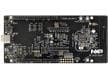
Caractéristiques de la carte
 MCXW72-LOC")
Schéma fonctionnel
 MCXW72-LOC")
Microcontrôleurs associés
NXP Semiconductors Microcontrôleurs MCX W72x
Il offre un coeur Arm® Cortex®-M33 de 96 MHz combiné à un sous-système radio multi-protocole.
Outil de développement
NXP Semiconductors Carte de développement de microcontrôleur (MCU) FRDM-MCXW72
Une carte de développement compacte et évolutive pour un prototypage rapide du microcontrôleur (MCU) sans fil MCX W72.